Description
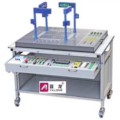
YL-JTD Three-dimensional Traffic Lights Trainer is a model which simulates the real road traffic lights. It is designed as per the combination of actual production need and professional job skill requirement.
The control system adopts module combination type, and is composed by the PLC module, button module and power modules and other components.
Functional Features
Panel is mainly composed of control button, control input, signal output, common port and
power output.
1. Control button: composed of start button, stop button, manual button, automatic button and 4 sidewalk call buttons, and 8 buttons are self-reset type push button;
2. Control input: composed of start terminal, stop terminal, manual terminal, automatic terminal, 2 sidewalk call terminals, 2 time control signal terminal, and connect with the input terminal of PLC module;
3. Signal output: composed of 8 traffic light wiring terminals at east and west, 8 traffic light wiring terminals south and north, 4 time control signal terminal, and connect with the output terminal of PLC module;
4. Common port: input common terminal built from buttons common terminals in series, so that the port can be connected to +24 V or 0V; output common terminal built from each traffic lights cathode (two-color light-emitting diode) in series, so the port can only be connected to +24 V;
Note: output common port can only connect to +24V, either transistor type or relay type PLC.
5. Control requirement: It has indication and control functions, and has four-direction straight and turn (red / yellow / green) indicator display module, four-direction digital countdown display module, and four-direction sound instruction module; control by the start / stop button, manual / auto button, crosswalk signal buttons.
6. Control scheme: The control scheme is controlled by the 8 input points (8 control buttons) and 16 output points of traffic lights (red / yellow / green indicator lights of left, straight, right line on the east-west lane; red / yellow / green indicator lights of left, straight, right line on the north-south lane; red / green indicator lights of east-west straight sidewalk; red/ green indicator lights of north-south straight sidewalk), four digital countdown output points (north-south timing and east-west timing), and three audio outputs (left line,straight-line and right line voice control).
List of Experiments
1. Control circuit installation project Select the device configuration PLC modules, power modules, can accomplish the following PLC application technical tasks.
- Modules expansion and installation training;
- Control circuit connection and commissioning training;
2. PLC programming project
- Main road traffic lights workflow programming training;
- Main road red, green and yellow lights workflow programming training;
- Main roads and sidewalks traffic lights workflow programming training;
- Main roads and sidewalks red, green and yellow workflow programming training;
- Main road red, green, yellow lights and digital countdown display workflow programming training;
- Main road and sidewalk traffic lights, digital countdown display workflow programming training;
- Main road red, green and yellow lights, digital countdown display and sidewalk traffic lights
workflow programming training;