Description
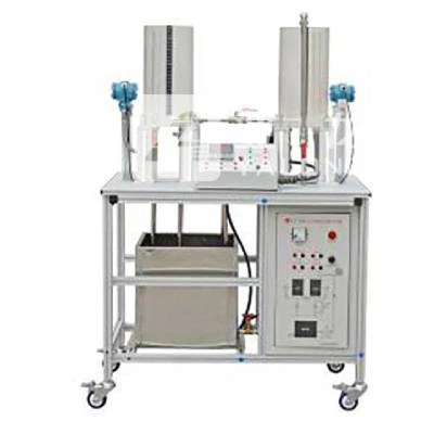
This YL-367 PLC Double Capacity Tank Trainer uses a double-capacity water tank as the control object, and the liquid levels H1 and H2 of the water tank are used as the controlled quantities. The change of the liquid level in the water tank is converted into a 4-20mA standard electric signal by the pressure sensor, and all I/O interface signals are respectively led to the control surface, which is convenient for the access and use of various controllers.
The entire experimental system flow is shown in Figure 1. The experiment object is a double-capacity water tank. The experiment is equipped with two control water tanks, water storage tanks, diaphragm pumps, liquid level transmitters, solenoid valves for switching pipeline states and other components. The entire experimental system adopts an integrated structure and is open on all sides, which not only ensures the clean and beautiful appearance of the experimental system, and meets the aesthetic requirements of modern laboratories, but also allows students to see each component of the experimental system and enhance students’ perceptual understanding of the experiment.
The experimental water is supplied to the control water tank by the driving amplifier through the diaphragm pump and the valve. The entire pipeline system can be combined into different experimental loops through the on-off switching of the solenoid valve.

Figure 1 Schematic diagram of the experimental process
Generally, the control parameters of industrial objects vary in a wide range. The experiment is designed to provide setting options and PID parameters to meet different control requirements by setting different parameters.
This YL-367 PLC Double Capacity Tank Trainer has different controlled models, either first-order (single-capacity) or second-order (dual-capacity). Different experiments can be performed by switching through the man-machine interface.