Description
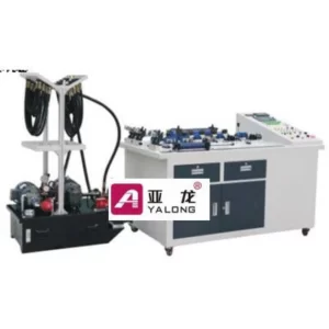
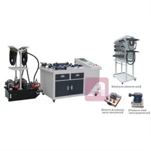
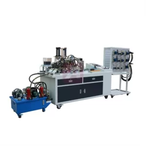
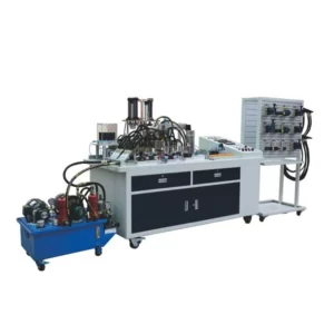
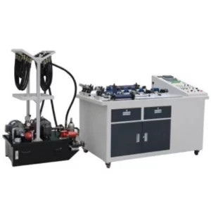
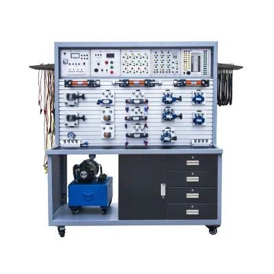
This PLC Hydraulic Practical Training Device can cover hydraulic transmission and transmission relay control, PLC control, sensor technology training. It is a integration of hydraulic technology and all kinds of modern control technology. This practical training platform is duo sided, thus one device can serve 2 students, and perform difference experiment in the same time, increases the utilization rate, and saves the training room space.
YL-381A PLC Hydraulic Practical Training Device content:
I.Experiment platform experiment content
Performance test of common hydraulic components (hydraulic pumps, relief valves, pressure reducing valves, throttle valves, etc.)
The hydraulic basic circuit test: (30 circuit)
1.Pressure control circuit
1)Overflow valve regulating circuit;
2)Overflow valve single stage remote pressure regulating circuit;
3)Multi-level overflow valve regulating circuit;
4)Overflow valve limit low voltage circuit;
2.Variable circuit:
1)Primary pressure reducing circuit;
2)Secondary pressure reducing circuit;
3)Multistage pressure reducing circuit.
3.Unloading circuit
1)3-position 4-way electromagnetic reversing unloading circuit;
2)2-position 3-way electromagnetic reversing valve unloading circuit;
3)Overflow unloading circuit
4.Voltage stabilizing circuit:
1)Hydraulic control check valve retaining circuit.
5.Pressure relief circuit:
1)Throttle relief circuit;
2)Sequence valve relief circuit.
6.Speed control circuit
1)Oil inlet throttling speed regulating circuit
2)Oil return throttling speed regulating circuit
3)Bypass throttling speed regulating circuit;
4)Speed regulating circuit controlled by speed regulating valve;
5)Differential connection accelerating circuit;
6)Accumulator increasing circuit;
7)Speed reduction circuit connected by series of electromagnetic valve and speed regulating valve;
8)Serial secondary feed circuit of speed regulating valve;
9)Parallel secondary feed circuit of speed regulating valve;
10)Serial secondary feed circuit of speed throttle valve;
11)Parallel secondary feed circuit of speed throttle valve;
12)2-position, 3-way controlled differential circuit;
13)3-position, 4-way controlled differential circuit;
14)Third feed circuit;
15)Differential operation commutation circuit;
7.Synchronous circuit:
1)Synchronous circuit controlled by throttling valve;
2)Two-cylinder synchronous circuit;
3)Synchronous circuit controlled by speed control valve;
8.Direction control circuit
1)Control valve reversing circuit;
2)Sequential action circuit for sequential valve control;
3)Sequential operation circuit with stroke switch control;
4)Pressure relay, control point, sequence, action circuit.
9.Locking circuit:
(1)Locking circuit:
(2)Locking circuit of hydraulic control check valve;
(3)Locking loop of check valve;
10.Balancing circuit:
1)Balancing circuit of hydraulic control check valve;
Balanced loop for sequential valve control.
II.PLC electrical control experiment:
1)PLC command programming, ladder diagram programming and other basic knowledge, learning and application;
2)PLC programming software learning and use;
3)PLC and computer communication, online debugging, monitoring;
4)Configuration software and PLC communication and monitoring experimental learning.