Description
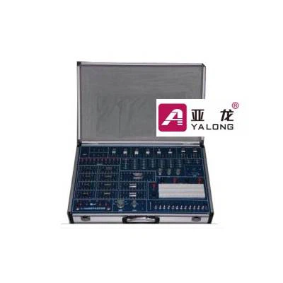
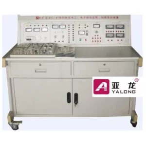
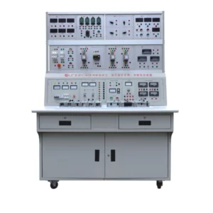
The experiment case uses sky blue case, inner side use 1 pc of 2mm thickness circuit board, which is fixed on the case with 9 self-tapping screw, to ensure the circuit board is fixed on the case safely. Circuit board supplies power by switch power, with strong current isolation and protection circuit. All observable and adjustable elements are distributed on the front of circuit board and the others are distributed on the back, which is convenient for the students to carry out the experiments.
1. Input power:~220V±10%, 50Hz, control the on-off by waveform switch (there is a power indicator light on the top right corner, when it is connected, indicator light will be on; when it is off, the indicator light will be off), power switch is set on the side of experiment case, which is convenient for the user to use.
2. DC output power: ±5V/1A, ±15V/0.5A, equipped with short circuit protection self-recovery circuit;
3. Logic level indication: 10 digits red LED indication logic level (there is the limit current inside),when input low level, LED is on;
4. Logic switch: 12 groups of independent logic level switch, which can output “0”“1” level(positive logic), it is high level“1” when the logic switch is pulled up; it is low level“0” when the logic switch is pulled down;
5. Single pulse source: can output positive and negative single pulse simultaneously, pulse amplitude is standard TTL level;
6. Audible alarm circuit: provide 1 pc of 8Ω/0.5W loudspeaker, output voice quality is better than buzzer;
7. Fixed pulse: output 1HZ, 1KHZ,1MHZ, three kinds of pulse, range is the standard TTL level, generated by SCM circuit;
8. Adjustable pulse output: 1Hz~1MHz continuously adjustable pulse output, roughly adjust the frequency with 6 levels with change-over switch, and fine tune the frequency through multi-circle potentiometer;
9. Nixie tube display: 3 groups of 2 digit DCB code input nixie tube display (CD4511 drive), 1 group of 2-bit independent nixie tube (set with current limited resistance ), input 7 segment numerical code can display the number, you can either use the positive or negative nixie tube;
10. IC base:DIP14*4, DIP16*4, DI20*2, DIP28*1;
11. resistor-capacitor element: onboard with many resistance, capacitance, potentiometer, LED;